![]() |
The most basic description of the antenna is that it is a shortened dipole.
Whatever you know or can learn about shortened dipoles applies here.
I chose the dipole configuration because I wanted to be able to use it in
environments where the questionable availablity and quality of a suitable
ground plane make use of a vertical problematic. The desire for effective
NVIS coverage strongly militates against a vertical. I also wanted an antenna
that requires a single support that would be quick and easy to assemble and disassemble
in the field. Other desirements include an antenna that can be effective without
an matching network.
The dipole center is one of the most interesting parts of the mechanical design of a diople. Folks building full sized dipoles are faced with the chore of connecting the two sides of their dipole to their feedline in a way that the whole thing will not fall apart or be pulled apart. In my case, I bought a center mount that is derived from a standard truckers CB mirror mount antenna. In this particular incarnation, there are mounts for two mobile antennas instead of just one. In my case, both mounts are intended to connect directly to a wire and are insulated from the rest of the mount. |
![]() | The antenna center, pictured to the left, is the modified truckers mirror mount clamped to the end of a five foot steel TV antenna mast. The balun is attached to the mast with tie-wraps and the two mobile antennas are installed as shown. I have another five foot TV mast hoseclamped to the ladder of my RV. Its narrow end sticks out above the RV roof level by several inches. When in use, the TV mast with the antenna fits over the small end of the hoseclamped TV mast, placing the center of the dipole fifteen feet off the ground. When the RV is in motion, fifteen feet is too high to pass under many bridges and signs, so the antenna has to be uninstalled, leaving the hoseclamped mast which extends above the RV roof less than the TV antenna! |
|
![]() |
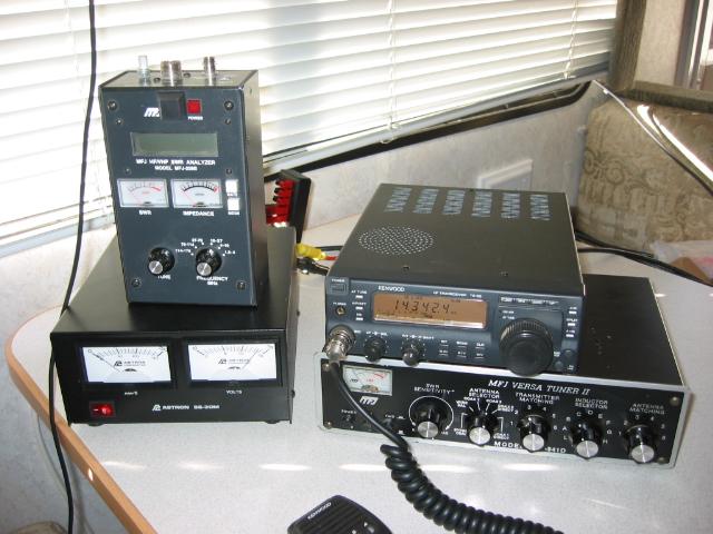
Finally, a picture of my station in the RV. The bandwidth of the loaded antennas isn't
very wide, especially for a solid state rig (Kenwood TS-50 in this case), so I use the
dreaded matching network to increase the usable bandwidth. The rig is happy anywhere
on the band but the coax losses rise faster as I move away from resonance than they
would with a full sized dipole.
The MFJ antenna analyzer has proved to be an exceptionally useful instrument. It makes it possible to find the resonant frequency of an antenna, which is a good thing to know. You really can't tell where resonance is with only an SWR bridge because minimum SWR and resonance are usually not at the same frequency. My philosphy is that, given a choice, I'd rather tune an antenna for resonance (zero reactance) and then let the matching network transform the antenna impedance into the 50 ohms the rig is designed for. If impedance at resonance is anywhere between 25 and 100 ohms, I don't need the matchbox at all. |