WB6W VERTICAL ANTENNA
May 1, 2007 -
Some folks have asked that I make progress and pictures of my vertical antenna project
available. This web page is my attempt to do just that. I'll update this page in a blog-like manner with text and
pictures as the project progresses. In most cases, pictures here will be fairly small in size.
Clicking directly on the picture will usually get a full sized copy of the image, some of which may need
a significant amount of time to download on dialup lines.
This project came to be because of the 2007 ARRL DX Contest, CW weekend. I only spent an hour or two in the
contest. However I was amazed that I was able to work Europe (POland) on 80m CW from the west coast using
a very low (less than 15') dipole. The DX bug bit (it does bite after all!) and I started thinking about
how I could get a better antenna for 80m DX.
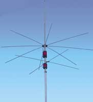 Without going into detail about the process and the reasons, I chose a
CushCraft MA8040T
loaded vertical. With a 2:1 SWR bandwidth of 100 KHz on 80m, it should be adequate for 80m CW given the new band alignment. My low dipole should be perfectly adequate for 75m SSB (typically NVIS) contacts. 40m operation is a bonus but not particularly important
in my case because I'm building mainly for 80m and because I also have a CushCraft R7 that adequately covers 40m.
It may be interesting to compare the two antennas on 40m though...
Without going into detail about the process and the reasons, I chose a
CushCraft MA8040T
loaded vertical. With a 2:1 SWR bandwidth of 100 KHz on 80m, it should be adequate for 80m CW given the new band alignment. My low dipole should be perfectly adequate for 75m SSB (typically NVIS) contacts. 40m operation is a bonus but not particularly important
in my case because I'm building mainly for 80m and because I also have a CushCraft R7 that adequately covers 40m.
It may be interesting to compare the two antennas on 40m though...
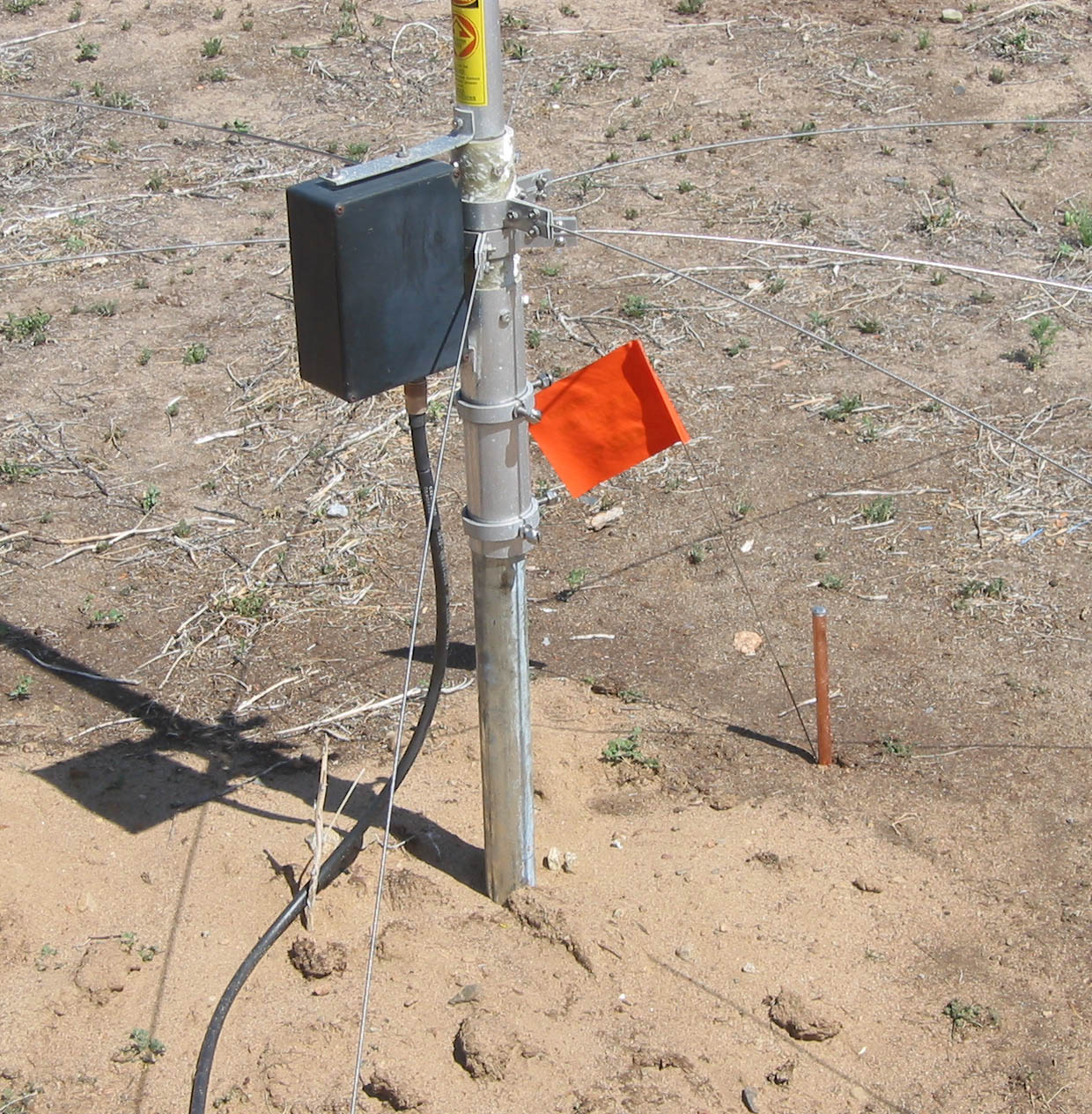
 I started by picking a place in my back yard where I'd have room for 66' radials. At that place I dug a
hole four feet deep. Into it I placed a five foot long 11/4" steel pipe.
My backyard soil is aluvial sand, electricaly poor and mechanically weak, so
I secured the bottom of the pipe with a 50 pound bag of "Quick Crete"
(and the appropriate amount of water), followed by a couple of feet of sand and topped with
another bag of "Quick Crete". The top few inches were filled with more sand.
I started by picking a place in my back yard where I'd have room for 66' radials. At that place I dug a
hole four feet deep. Into it I placed a five foot long 11/4" steel pipe.
My backyard soil is aluvial sand, electricaly poor and mechanically weak, so
I secured the bottom of the pipe with a 50 pound bag of "Quick Crete"
(and the appropriate amount of water), followed by a couple of feet of sand and topped with
another bag of "Quick Crete". The top few inches were filled with more sand.
 Local winds of 30mph are common and winds of 60 or 70mph occur once or twice a year.
That's the reason for the steel pipe, rather than the 1" electrical conduit the MSA8040 manual suggests.
It's also the reason for the cement.
Local winds of 30mph are common and winds of 60 or 70mph occur once or twice a year.
That's the reason for the steel pipe, rather than the 1" electrical conduit the MSA8040 manual suggests.
It's also the reason for the cement.
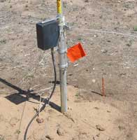
A week or so after the base was in, I put the R7 up for a mechanical checkout. I didn't have to
wait very long, the very next day it was subjected to winds between 20 and 30mph. The system passed
with flying colors.
Astute readers will note a short copper rod just to the right of the base.
That's the top 6" of an 8' ground rod, driven next to the base.
Once the MA8040 is assembled and installed, it will be the initial ground for the antenna.
With that ground, the MA8040 will be adjusted for an initial resonant frequency of 3535 KHz.
In this case, "resonance" means a purely resistive load. These measurements will
be done with my trusty MFJ-259B antenna analyzer.
Once that is done, the plan is
to remeasure the resonant frequency and feedpoint impedance after varying numbers of radials are
added and note the changes. I expect that, given the poor initial ground, the first feedpoint
impedance will be rather high, reflecting the high ground losses. As radials are added, I expect the
feedpoint impedance to drop and asymtoticly approach the radiation resistance of the antenna. Given that
it's a loaded antenna, Rr should be fairly low. I'll calculate an estimate later, but I expect to
get an Rr value somewhere between 10 and 20 ohms. More later, it's supposed to snow tomorrow.
May 2, 2007 - HOW MANY RADIALS AND HOW LONG? -
First off, a 23' vertical at 3.52 MHz has a radiation resistance of approximately 2.6 ohms.
Since the MA8040 has a capacity hat, this will be a lower bound. The upper bound will correspond
to an antenna twice as long, which has a radiation resistance of approximately 10.3 ohms.
Either way it's clear that minimizing ground loss will be very important.
It's also clear that the antenna will require some kind of matching network at the base.
In the best case from an antenna efficiency perspective a 1:5 impedance transformation
will be required.
The first cut at determining the answer to the radial question is to RTFM, the FM being
the MA8040 manual. The MA8040 is supplied with a 400' spool of wire for radials and the FM
calls for it to be cut into 4 35' lengths and 4 65' foot lengths, a total of 8 radials.
The FM does say, "More than the prescribed number of radials may be installed on the
MA8040V at your option in order to optimize radiation efficiency. However, note that
as radials are added, SWR may eventually increase to an unacceptable level..."
Given the 10 ohm (at best) radiation resistance, it's clear that at best the antenna
efficiency with the CushCraft recommended installation will be no better than 20% and
possibly as poor as 5%.
Adding radials will reduce the ground loss, thereby reducing the feedpoint impedance
below 50 ohms and so increase the SWR at resonance. Clearly, the CushCraft recommendation
is to optimize for low SWR at the expense of antenna efficiency. I should be able to do better than that.
My friend Alan Biocca WB6ZQZ pointed me to an
NCJ article
on selecting the optimum number of radials. In this case, "optimum" means best use of
a specific length of wire. The article goes on to optimize the number of radials, letting
the length of the radials be dependent on these two numbers. So more radials means shorter radials.
Note any conclusion based on this study that more radials than study optimum
are less effective needs to be tempered with the realization that more radials directly implies that they are shorter radials. The study is mute as to the value of having more radials that are the same length or longer.
In my case, I am constrained by the size of the property I have to install the ground system.
I have 2500' of wire - the hardware store was selling 500' lengths of #12 copper wire for $7 or so.
My main constraint is that I am real-estate limited to 66' radials. For 2500' of wire, this
means I will have 38 radials.
It turns out that the study optimum numbers are not to far from this. On 80m, the study calls
for approximately 25 80' radials for 2000' of wire or 17 58' radials for 1000' of wire.
Interpolating to a 66' radial, there should be 21 radials from 1386' of wire. Thus on 80m
I'm planning on twice as many radials as the study claims is optimum for a 66' radial.
The value of the extra radials will become apparent (or not) when I measure the feedpoint resonant impedance.
If twice as many radials have any effect, it will be reflected in a lower feedpoint impedance.
There are other considerations. For example, the ARRL Antenna Book says that the optimum count
for 1/4 wave radials is 90. This is very much at odds with the study results.
The reason for the discrepancy is not clear because the Antenna Handbook does not say what it
means by "optimum". However, my 38 radials is only a third of the optimum number according to the
ARRL book. This will provide room for additional real world experimentation.
Another consideration comes from the fact that both the study and the Antenna book recommendations are
based on a full sized 1/4 wave vertical. The MA8040 is a shortened antenna, being only
23' high. This corresponds to a less that .1 wavelength high radiator. According to the ARRL Antenna
Book, the "zone current" close to the antenna base will be more than 3 times what it is for a quarter wave vertical.
Thus, additional radials, even short ones, can be expected to improve the antenna efficiency.
 I started by picking a place in my back yard where I'd have room for 66' radials. At that place I dug a
hole four feet deep. Into it I placed a five foot long 11/4" steel pipe.
My backyard soil is aluvial sand, electricaly poor and mechanically weak, so
I secured the bottom of the pipe with a 50 pound bag of "Quick Crete"
(and the appropriate amount of water), followed by a couple of feet of sand and topped with
another bag of "Quick Crete". The top few inches were filled with more sand.
I started by picking a place in my back yard where I'd have room for 66' radials. At that place I dug a
hole four feet deep. Into it I placed a five foot long 11/4" steel pipe.
My backyard soil is aluvial sand, electricaly poor and mechanically weak, so
I secured the bottom of the pipe with a 50 pound bag of "Quick Crete"
(and the appropriate amount of water), followed by a couple of feet of sand and topped with
another bag of "Quick Crete". The top few inches were filled with more sand.
 Local winds of 30mph are common and winds of 60 or 70mph occur once or twice a year.
That's the reason for the steel pipe, rather than the 1" electrical conduit the MSA8040 manual suggests.
It's also the reason for the cement.
Local winds of 30mph are common and winds of 60 or 70mph occur once or twice a year.
That's the reason for the steel pipe, rather than the 1" electrical conduit the MSA8040 manual suggests.
It's also the reason for the cement.